Unit D: Electrical Principles & Technology
Review of the Atom
protons have a positive charge
electrons have a negative charge
neutrons have no charge (neutral)
atoms may gain or lose electrons and become ionized
charged particles can either repel or attract each other
Static Electricity
Charges:
Objects can carry a negative or positive charge
when there are more protons than electrons, the object has a positive static charge
when there are more electrons than protons, the object has a negative static charge
Very important to note, electrons will transfer from object to object, not protons.
Ex. When you are rubbing your feet on a carpet to “build up” charge you are wiping electrons off onto the carpet not protons.
Neutral charge:
When an object contains equal numbers of protons and electrons
Most objects have an equal amount of positive and negative static charge so they are neutral overall
That is why you do not receive a spark from contacting items around the house.
Law of attraction:
Opposite charges attract each other, like charges repel each other (No this does not apply to love)
ACTIVITY
Note that the balloon and sweater have equal amounts of positive & negative charges to start off, both are neutral
Rub the balloon on the sweater, what happens to all the electrons from the sweater?
Move the negatively charged ballon towards the wall, what happens to the charges in the wall?
Static Electricity:
A build up of electrons caused by friction, a negative charge builds up, then discharges when near an object that will accept or donate electrons. Electrons do not flow continuously, they are discharged all at once. Zap!
Example of Electrical Discharge
Build up of charge - rubbing feet on carpet makes the electrons move from your skin to your carpet
Holding charge - your skin has lost electrons, thus skin now has a positive charge (less electrons)
Transfer of charge to another object - touching metal or someone else cause electrons to move from the object to your skin
Electrical discharge - electrons transfer over to new object to neutralize charges quickly resulting in a spark or a small shock
Examples of static Electricity
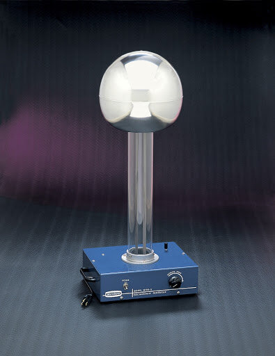
Other examples of static electricity discharging include: lightning, Van de Graaf generator, Tesla coil
a Van de Graaf generator uses friction from a belt being rubbed to build up a static charge
The flow of Electricity

Much like a stream where moving water produces the current, an electrical current is created by moving electrons (protons do not flow)
Electrical Current:
The continuous flow of electrons through a conductor, note that protons stay in place, electrons do the moving, not the protons!
rivers have currents of water flow through them, conductors have currents of electrons flowing through them
static electricity doesn’t flow continuously hence it’s static not current (using the water in a stream metaphor, static electricity would be a puddle)
small devices (cell phones, MP3 players etc) use very little current
large devices (cars, generating stations) use a lot of current
conductors:
A material that freely allows electrical charge to move through (think of it like a stream with no boulders obstructing the flow)
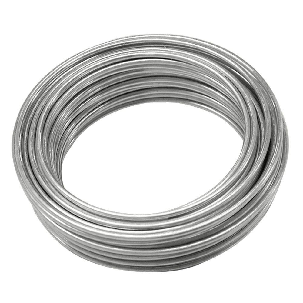
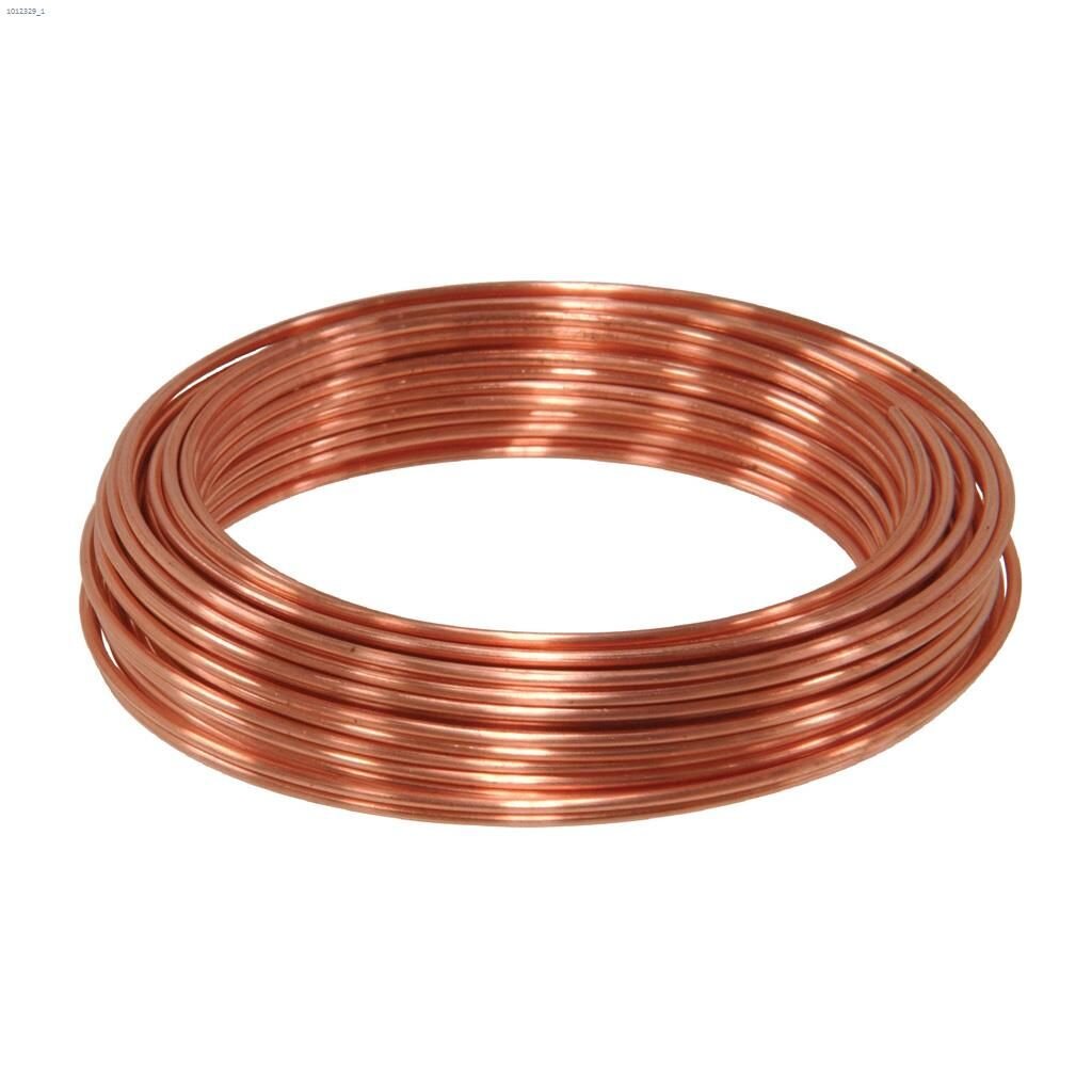
Good conducting materials:
Steel
Copper
Gold
Salt Water
Silver
Moist materials tend to conduct better than dry materials!


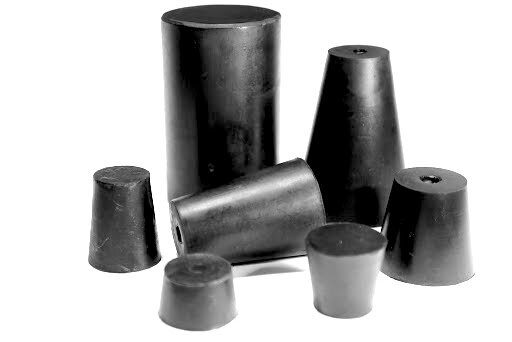
Insulators:
A material that does not freely allow the movement of an electrical charge (think of it like a stream with many boulders impeding the flow)
Good insulating material:
wood
plastic
rubber
air
glass

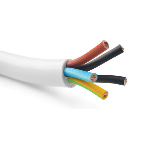

To prevent injury and short circuits many conductors are wrapped in an insulator (Hence why all power cords are coated in plastic)
If an insulator is damaged, shock may be possible
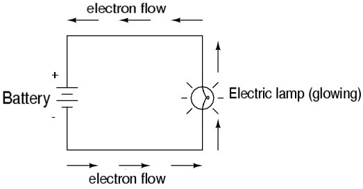
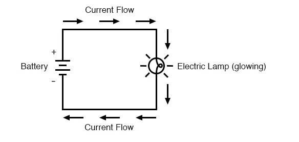
Circuit:
A circuit is the continuous path that an electrical current flows through

A CIRCUIT WHERE ELECTRICITY FLOWS
It is made up of:
Conductor – wires
Load – device that draws electricity (ex. Lightbulb)
Energy source – battery
CONVENTIONAL CURRENT

DEPICTION OF ELECTRON FLOW
Remember two things:
Electrons flow through conductors, not protons!
Law of attraction states that same charges repel, while opposite charges attract. (negative charges move away from other negative charges and are attracted to positive charges
Electron current/flow:
Electrons which are negative (-) move away from the negative terminal towards positive terminal (+). So electrons flow from negative to positive.
Conventional Current:
Way back in the day, before scientists fully understood electricity they hypothesized that electrical current flowed from positive terminal to negative terminals, they were dead wrong.
Unfortunately to this day we are stuck with this nomenclature
When using the general term “current” it applies to Conventional Current which flows from positive to negative, If I want to discuss electron flow I would use the term “electron current”
To summarize, current = conventional current not electron flow, and “current” flows from positive to negative.
Voltage vs. Amperes


Voltage or potential difference:
The difference in charges between two points, this difference (also known as potential difference) describes how much electrons want to flow in a circuit from the negative terminal to the positive terminal.
The unit of voltage is the volt, it is denoted with a capital ‘V’
Voltage is like the ‘pushing’ force for electrons, the higher the voltage the more the electrons want to ‘push’ from one point to the next. If the pushing force is high enough electrons will even pass throug insulators (Ex. lighting passing through air)
Amperage:
The rate at which electrical current flows, amperage measures how much electricity is passing through a conductor.
The unit of amperage is the amperes, it is denoted with a capital ‘A’, many people say ‘amps’ for short
Electrical Safety

REASON WHY YOU SHOULD'NT FLY A KITE NEAR ELECTRICAL WIRES
Short Circuit:
A short circuit is an unintended path for electricity
electric current will always take the shortest path available
if a power line is down, electricity will not flow because the circuit is considered “open”
if you go too close you will “close” the “open” circuit and the electricity will flow through you!
Dangers of Electrical Shock

Both voltage and current can be dangerous!!
Skin is a bad conductor of electricity therefore a power supply voltage must be higher than 40 volts to “push” a fast flow of charges through a human body and cause electrocution
However, high voltage is only dangerous if there is a flow of electrons (current) you can get a zap of 10,000 volts from scuffing your feet on a carpet and then touching a door knob but thankfully death doesn’t happen because there is no current!
Common Voltages !
Voltage (volts)
human cell 0.08 V
microphone 0.1 V
photocell 0.8 V
AA battery 1.5 V
electrochemical cell 1.1 V to 2.9 V
electric eel 650 V
standard wall outlets in house 120 V
standard wall outlet for oven or dryer 240 V
generators in power stations 550 V
Dangers of Amperes
High voltage is dangerous, however it is not the voltage that will harm you, it is the amperes! In other words how much electrical current flowing through you will harm you, not the electrical potential.
1000 milliamps = 1 ampere
less than 10 mA (0.01 A) - Electrical shock is felt.
between 10 to 20 mA (0.02 A) - Painful shock, but muscle control is not lost.
between 20 to 75 mA (0.075 A) - Serious shock, including a painful jolt and loss of muscle control, at this point muscles will not let go of wire!
between 75 to 100 mA (0.1 A) - Heart muscles begin to convulse
between 100-200 mA (0.2 A) - Heart attack may occur/death.
At a current lower than 10 mA, even a high voltage power supply cannot electrocute you!
Electric Current Ratings
Common Electrical Devices and their corresponding currents
electronic wrist watch 0.00013 A (0.13 mA or milliamps)
electronic calculator 0.002 A (2 mA)
LED light bulb 0.02 A (20 mA)
electric clock 0.16 A (160 mA)
light bulb (100W) 0.833 A
television (color) 4.1 A
vacuum cleaner 6.5 A
oven element 11.4 A
toaster 13.6 A
car starter motor (V-8) 500 A
too much electricity flowing through a person’s body can cause the following:
pain
loss of muscle control, muscles will in fact tighten
burns
damage to the heart
death
Protection from Electricity
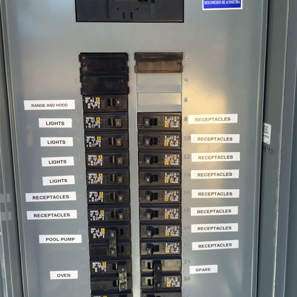
Our homes and the devices we use are equipped with safety features to protect us from electric shocks many appliances and devices have three-pronged plugs the third prong connects the device to the ground wire of the building to provide another pathway for electricity just in case of a short circuit
The current in a lightning strike can be 30 000 A (current as low as 0.1 A can be fatal) lightning rods are placed on the top of tall buildings etc and they are connected to the ground by a wire the lightning strike is then carried to the ground to be discharged.
Q: What happens when too much current passes through a conductor?
A: The conductor can get too hot, it can melt, and start a fire.
Thankfully we have the following technology to make sure we don’t unwillingly start any fires.
Fuses:
Interrupts a circuit when too much current flows through it. Fuses have a wire in them that melts if the current gets too high. When the wire melts it interrupts the flow within the circuit.
Circuit Breakers:
Found in all buildings (including homes). Circuit breakers interrupt a circuit when too much current flows through it. Breakers have a wire that ‘trips’ a switch if the current gets too high (the wire gets too hot).
both a blown fuse and a tripped breaker will open the circuit, not allowing electricity to flow
Cells & Batteries

Battery:
A device that stores electrical energy in the form of chemical energy. It contains cells where electrons move via a conductor from one type of metal to another type of metal.
4 Parts of a voltaic cell:
Two electrodes, essentially two pieces of metal, both have to be different metals. Why??
A paste that contains ions, the electrodes are submerged in this paste. This paste is called an electrolyte.
A conductor which connects the electrode giving up electrons to the electrode that is taking electrons.
A porous membrane (sometime called a salt channel)
Dry Cells:
Electricity producing cells, “dry” because the electrolyte inside is a paste
Wet Cells:
Electricity producing cells, “wet” cells because the electrolyte (ex H2SO4(aq)) is a liquid.
Use in batteries for cars.
Cheaper and easier to make than dry cells but you have to be careful not to spill the electrolyte which is highly corrosive
Rechargeable Cells
The chemical reactions inside a rechargeable cell are reversible, these are called secondary cells
Can be used to store energy from an outside source (solar panels)
Electrochemistry
Electrochemistry:
The study of chemical reactions that involve electricity
electrolysis:
An industrial process that is used to separate useful elements
(ex) hydrogen and oxygen gases for fuel for the space shuttle
electroplating:
Uses current to deposit atoms of a metal onto an electrode
(ex) silver plating
electrorefining:
Process that removes impurities from a metal
Controlling the Flow of Electrical Current
Recap:
Insulators - Electrons in insulators are tightly bound to the positive nucleus of their atoms and they cannot flow
Conductors - Electrons are not tightly bound and are free to move (with some resistance)
Superconductors:
Superconductors are perfect conductors
The electrons have no resistance to flow
The temperature must be very low (close to absolute zero) for superconductivity

VARIOUS RESISTORS, THE DIFFERENT COLOUR BANDS CORRELATES TO VARIOUS RESISTANCE AMOUNTS
Resistance:
Is a measure of how difficult it is for electrons to flow through a substance
Resistance is measured in Ohms (Ω)
The resistor gains energy from each electron that passes through it
This energy can be released as heat or light
(ex) in a space heater or light bulb, liquids can also be good resistors
Adding resistors to a series line consecutively increases the total resistance of that line...
(ex) Total (Ω) = Resistor1 (Ω) + Resistor 2 (Ω) + Resistor 3 (Ω)....
(ex) Total 150 Ω = R1 (50 Ω) + R2 (75 Ω) + R3 (25 Ω)
Resistors:
Resistors allow only a certain amount of electric current to pass
Switches:
Used to control the flow of electricity through a circuit
When the switch is on, two conductors are pressed together, closing the circuit and making electricity flow
switches are enclosed in an insulating case for protection
Variable Resistors:
Allow the gradual adjustment of electric current

THE 'OLDSCHOOL' METHOD OF DRAWING A VARIABLE RESISTOR
also called rheostats
made of one single curved resistor
a dial changes the amount of the resistor that is used
Transistors:
A switch that is controlled by an electric input, however it does not have any moving parts
Modelling & Measuring Electricity
Modelling Electricity
Because electricity “flows”, we can use water to be a model for how electricity behaves
A waterfall is a good model for voltage a
A change in elevation allows the water to flow because of gravitational potential energy in a circuit, a change in potential difference from a battery allows the electrons to flow
The higher the potential difference (waterfall) the higher the voltage (energy)
A pipe is a good model for resistance and current
(Ex) If you use a pipe to drain a pool, a longer, thinner pipe will have the most resistance and will drain it much slower (lower current)
If you use a short, wide pipe, it will have less resistance and will drain faster (higher current)
Ohm’s Law
Georg Ohm found a relationship between voltage (V), current (I) and resistance (R):
Resistance in a conductor is constant
Current is directly proportional to voltage
Thus...Increasing the voltage in a conductor will increase the current since resistance is constant
where: V = voltage in Volts (V)
I = current in Amperes (A)
R = resistance in Ohm’s (Ω)
V = IR
Example 1
Calculate the voltage if the current is 0.5 A and the resistance is 2.0 Ω.
I = 0.5 A , R = 2.0 Ω, V = ?
V = IR
V = (0.5 A)(2.0 Ω)
V = 1.0 V
Example 2
Calculate the current if the voltage is 1.2 V and the resistance is 0.6 Ω.
V = 1.2 V, R = 0.6 Ω, I = ?
V = IR or... I = V/R
I = 1.2V/0.6Ω
I = 2.0 A
Example 3
Calculate the resistance if the current is 1.1 A and the voltage is 2.2 V.
V = 2.2 V, I = 1.1 A, R = ?
V = IR or... R = V/I
R = 2.2V/1.1 A
R = 2.0 Ω
Test Meters

A TYPICAL MULTIMETER
All test meters use a small amount of current
Test Meters:
Measures the following
voltmeter - potential difference between two points in a circuit (voltage)
ammeter - electrical current which is the rate of flow of electricity
galvanometers - measures small amounts of currents
ohmmeters - measures resistance
multimeters - all in one measuring tool, measures voltage, current or resistance in a circuit
Analyzing Electrical Circuits
Circuit Drawings
Engineers and scientists use special symbols to draw, plan and analyze electrical circuits
Circuits have 4 basic parts:
Source – provides energy and a supply of electrons
Conductor – path for current
Switch – controls current flow
Load – converts electrical energy into another form of energy
you can draw simple circuits using the common circuit symbols

Series Circuits

A SERIES CIRCUIT - CLOCKWISE WE HAVE THE BATTERY, A LAMP, ANOTHER LAMP, A AMMETER, AND A SWITCH.
Series circuit:
A circuit which has all loads in one single loop
electrons have only one path the follow
an interruption results in no flow of current (Ex in the example above, I can unscrew one of the lamps and the other lamp will not remain lit)
adding loads increases the resistance in the circuit
Parallel Circuits

A PARALLEL CIRCUIT - TOP TO BOTTOM WE HAVE A BATTERY, A LAMP, AND ANOTHER LAMP.
parallel circuit:
A circuit which has more than one pathway for the electricity to flow through
loads in separate loops will not interfere with each other (Ex. in the example above, I can unscrew one of the lamps and the other lamp will remain lit)
loads in separate loops reduces the resistance in the circuit
Applications of Circuits

CHRISTMAS LIGHTS THAT USE SERIES LIGHTING - YOU GET WHAT YOU PAY FOR
House wiring uses parallel circuits…you don’t want one light bulb burning out to shut down all power!
Houses also have a circuit in series so that you can turn off all power at once if needed
Christmas lights use parallel wiring so the bulbs will stay lit even if one burns out
Microcircuits (microelectronic circuits) are extremely small circuits that are made up of transistors and resistors
Assignment - Drawing circuits
Draw each of the following circuits:

SUBMIT IN THIS FORMAT!
1. Single cell, 1 switch controls 1 motor, a separate switch controls 2 lamps.
2. 2 cell battery, 1 resistor, 2 lamps, all controlled by 1 switch.
3. Single cell, 3 lamps, 1 ammeter, 1 switch that controls only the ammeter and a lamp.
4. Single cell, parallel circuit, with 3 lamps, 1 motor, and 1 voltmeter, all controlled by one switch.
5. 3 cell battery, a switch that only controls 1 motor as well as an ammeter. A variable resistor that only controls 2 lamps. One voltmeter that measures the voltage of the entire circuit.
6. 2 cell battery, a variable resistor that only controls the speed of a motor, as well as a switch which will turn the motor on/off. A second switch that controls 3 lamps an ammeter and a resistor which has the resistance of 10 ohms.